Bridge Component Layout Dialog Box
The Bridge Component Layout dialog box allows you to define the physical location, bearing, and connection types for abutments, piers, and span hinges. The stationing for the beginning-of-bridge (BB) and the end-of-bridge (EB) is also defined in this dialog box. You may modify the physical locations (using distances instead of stationing), bearings, and connections to be used in the structural analysis model using the Superstructure dialog box located in the Model tab. To open the Bridge Component Layout dialog box, click the Layout button on the Geometry tab.
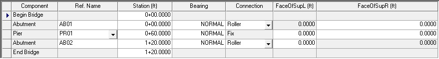
The Bridge Component Layout dialog box is used to define the physical location and attributes of superstructure connections. The physical location of these connections is specified using a stationing value from a common datum. The bearing of the superstructure connection is specified using a N-S degrees-minutes-seconds E-W value. You may also use the keyword NORMAL to denote a normal or radial connection or the command SKEW x.x where x.x is a positive or negative skew (from a normal) angle. Refer to the Technical Discussion below for details on how CIP RC/PT Girder makes use of the bearing. The connection between the superstructure and abutments and bents, and between adjacent span segments for span hinges, is specified by using either a keyword (e.g., free, roller, pin, fix) or by using a set of spring constants. The spring constants are specified as terms of a 3-by-3 stiffness matrix. You may use just the diagonal terms or use both diagonal and off-diagonal terms (i.e., a fully coupled stiffness matrix) to realize any kind of connection.
The Ref. Name attribute of a connection takes on a different meaning depending on the connection item. For piers, it is used to refer to a pier defined in the Pier and Column Definition dialog box. For all other items, it is used to give the item a convenient label for informational purposes. It is not used to refer to a defined abutment or span hinge.
FaceOfSupL and FaceOfSupR define the faces of support to the left and right, respectively, from the center line of abutments and piers. by default, these values are set to zero but can be changed by the user. These values are used in selecting the critical sections for checking stresses and for calculating flexure and shear strengths. When existing files are read, these values are set to zero for abutments and to one half the pier column dimension in X-direction for piers
Please note, the analysis cannot be run until all piers used in the Bridge Component Layout dialog box have been defined in the Pier and Column Definition dialog box.

CIP RC/PT Girder checks the value of the stationing of connection items and marks items with equal stationings in red. The exception to this check is for the beginning-of-bridge and the end-of-bridge. The OK button becomes disabled until all red stationings have been corrected.
Adding Abutments
A bridge in CIP RC/PT Girder may have from zero (0) to two (2) abutments. After the second abutment is added, the Add Abutment button becomes disabled. The stationing of the first abutment may be equal to or greater than the beginning-of-bridge and the stationing of the second abutment may be less than or equal to the end-of-bridge. Cantilevered end spans are defined by specifying the stationing of the beginning-of-bridge or the end-of-bridge to be different than the abutment stationing.
- Select one of the existing rows in the grid by clicking anywhere in its row. A blue arrow displays on the left side of the grid to mark the selection.
- Click the Add Abutment button. This adds an abutment after the selected component. The value of the stationing for the newly added abutment will be at the midpoint stationing between two existing components or, when placed after the last component, equal to the stationing of an existing component.
- Enter the abutment values in the grid. A definition for each parameter can be found below.
Adding Piers
A bridge in CIP RC/PT Girder may have from zero (0) to an unlimited number of piers. The Ref. Name attribute refers to a pier defined in the Pier and Column Definitions dialog box. If CIP RC/PT Girder does not find a match on a pier, i.e., there isn't a pier defined in the Pier and Column Definition dialog box with the same name (reference names are case-sensitive), then a continuous beam model is generated using the specified connection as the connection between the beam (i.e., superstructure) and the boundary.
- Select one of the existing rows in the grid by clicking anywhere in its row. A blue arrow displays on the left side of the grid to mark the selection.
- Click the Add Pier button. This adds a pier after the selected component. The value of the stationing for the newly added pier will be at the midpoint stationing between two existing components or equal to an existing component's stationing when placed after the last component.
- Enter the pier values in the grid. A definition for each parameter can be found below.
Adding Hinges
You can add up to two (2) hinges per span. CIP RC/PT Girder will mark the stationing of span hinges in red for spans that have more than two hinges. The OK button will become disabled until you correct the stationing of the indicated span hinges.
- Select one of the existing rows in the grid by clicking anywhere in its row. A blue arrow displays on the left side of the grid to mark the selection.
- Click the Add Hinge button. This adds a hinge after the selected component. The value of the stationing for the newly added span hinge will be at the midpoint stationing between two existing components or equal to an existing component's stationing when placed after the last component.
- Enter the hinge values in the grid. A definition for each parameter can be found below.
Deleting Components
The purpose of the Delete Component button is to remove a superstructure connection from the bridge. All superstructure connection items, e.g., abutments, piers (bents), and span hinges can be deleted but the beginning-of-bridge and end-of-bridge cannot. If you select either the BB or EB, the Delete Component button will be unavailable.
Grid Definitions
| Setting | Description | ||||||||||||
|---|---|---|---|---|---|---|---|---|---|---|---|---|---|
| Component | This non-editable field lists the component types (e.g., beginning-of-bridge, abutment, pier, hinge, and end-of-bridge). | ||||||||||||
| Ref. Name | This attribute of a superstructure connection takes
on a different meaning depending on the connection item. For piers, it is used
to refer to a pier defined in the Pier and Column Definitions dialog box. For
all other items, it can be used to give the item a convenient label for
informational purposes. It is not used to refer to a defined abutment or span
hinge.
If CIP RC/PT Girder does not find a match on a pier, i.e., there isn't a pier defined in the Pier and Column Definitions dialog box with the same name (reference names are case-sensitive), then a continuous beam model is generated using the specified connection as the connection between the beam (i.e., superstructure) and the boundary. |
||||||||||||
| Station | Enter the station of the component. | ||||||||||||
| Bearing | Enter the bearing of the centerline of the component using either a N-S degrees-minutes-seconds E-W value, the keyword NORMAL or the command SKEW x.x where x.x is a positive or negative skew (from a normal) angle. | ||||||||||||
| Connection | Select the connection type from the drop-down list.
|
The Connection field for Piers will contain the connection type of Fix and will be disabled when the pier Ref. Name refers to an Integral type pier or bent since integral bents are always fixed to the superstructure. If a pier Ref. Name refers to a drop-cap pier or bent with a non-fixed connection and it is subsequently changed to an Integral pier, the connection type will be changed to Fixed.
Technical Discussion
The Bridge Component Layout dialog box is used to define the physical locations and attributes of superstructure connections. You can modify the physical locations (using distances instead of stationings), bearings, and connections to be used in the structural analysis model using the Superstructure dialog box located in the Model tab. You cannot add superstructure connections using the Superstructure dialog box since it is intended to modify existing physical layout items, not create them.
This makes for a clear separation between the definition of the bridge (as defined in the Bridge Component Layout dialog box) and the desired model (as defined using the Superstructure dialog box) used for analysis. You define the physical bridge once and, thereafter, you make any number of changes to the analysis model without affecting the physical definition. Once any changes are made to the physical description in the Bridge Component Layout dialog box, e.g., changing a stationing, adding or deleting a pier, the information in the Superstructure dialog box is replaced with the new physical bridge information.
The default information used for the analysis model is the physical model. Therefore, if you do not modify the physical bridge description using the Superstructure dialog box, the analysis model generated is based on the physical description of the bridge.
CIP RC/PT Girder generates a slight variation of a plane frame model for analysis. This is done to account for the effect of skewed supports on the analysis. Skewed supports couple bending moment and torsion in the superstructure and, therefore, the superstructure is modeled using a plane-frame bending element with a torsional degree-of-freedom (DOF). CIP RC/PT Girder automatically calculates the torsional moment of inertia of the superstructure and uses it in the computation of the torsional stiffness coefficient. All transverse displacements are constrained.
The connection specification in the Bridge Component Layout dialog box defines the type of force release between the superstructure and abutments and piers, or between adjacent span segments at span hinges. The connection is modeled using a zero-length, two-node "super-element" that contains two support-bearing elements spaced transversely along the skew axis of the support. In this way, the superstructure "feels" the presence of the skewed support.
The stiffness values of the support-bearing elements are assigned appropriate values depending on the specified connection. For example, a pin connection is realized by assigning large values to all translational stiffness terms for the support bearings. The vertical stiffness term for each support-bearing element is always a large value in order to maintain continuity of torsion. In essence, this assumes that the superstructure is wide enough to always transmit torsion into the substructure or across a span hinge.
The effect of modeling the connection this way is that, when there is a skew angle at a support, an off-diagonal or coupling stiffness term between the bending and torsional diagonal stiffness term is produced. A large skew angle results in a strong coupling between bending and torsion in the superstructure. Box girder bridges have closed, thin-walled cross sections and are torsionally stiff. Therefore, the overall stiffness, i.e., the three-dimensional stiffness, of the substructure is included in the plane-frame model of the bridge.
The columns in the substructure are modeled as space-frame bending elements (6 degrees-of-freedom per node), which are then statically condensed down to a single point of connection at the location where the pier attaches to the bottom of the superstructure connection. Therefore, the effects of skewed multicolumn bents and foundation spring constants (which are oriented in the coordinate system of the pier) are accounted for in the modified plane-frame superstructure model.
Due to the separation of the physical bridge description in the Bridge Component Layout dialog box and the modeling information in the Superstructure, you can correctly describe the physical bridge and make modeling changes to it in order to obtain the model you deem appropriate for a given situation. Consequently, you can specify the actual bearings of supports and span hinges, and if that results in a skew angle (this depends on the alignment and the bearing) and you don't want to include the effects of coupling between bending and torsion in the superstructure, you can change the bearings in the Superstructure dialog box in order to eliminate any skew angles.